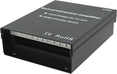
Rainproof Power Amplifier
| Place of Origin | China |
|---|---|
| Brand Name | okled |
| Model Number | AP200 |
| Input Voltage | DC12V-24V |
| Correlated Color Temperature | -20-60°C |
| Inquiry | |
Detailed Product Description
Product Specification
Name: Rainproof Power Amplifier
Model: AP200

Summarization
Rainproof power amplifier is one type of waterproof outdoor product in our company, suit for PWM control led controller, it can amplify the power of LED controller, each time add one amplifier, the connecting number of led will be more than twice to three times, and can cascade, in theory, numerous amplifiers can be connected. It is convenience for different voltage, high power and small power LED lamps and lanterns unified control. Whether our company's products or any other company's products, as long as it is PWM control, voltage appropriate, all can use this series power amplifier. Using high speed light lotus root design, can achieve very low delay time, to ensure that when many sets of cascade, it can keep pace with host.
Technical parameters
l Working temperature: -20-60 °C
l Working voltage: DC12V-24V
l Signal voltage: DC12V-24V
l Input signal: PWM dimming signal
l Dimming range: 0.1%-100%
l Net weight: 456g
l Gross weight: 501g
l External dimension: L136mm*W105mm*H45mm
l Packing size: L142Χ W118 Χ H50 mm
l Connect terminal: barrier type terminal, screw connect mode, terminal caliber 7mm
l Connect mode: common anode
l Max. output current: 3*8A
l Output power: 12V:<288W, 24V:<576W
l Protection grade: IP33
External Dimension:

Interface instruction:

1>: Power supply input voltage cathode
2>: Power supply input voltage anode
3>: Load output common anode public pole
4>: R channel load output cathode
5>: G channel load output cathode
6>: B channel load output cathode
7>: R channel input signal cathode
8>: G channel input signal cathode
9>: B channel input signal cathode
10>: Input signal common anode public pole
Installation Method and Operating Instructions:
Step 1: Tighten the screws on the wall with a screwdriver. And make the head of screw and the wall at a distance of 2.5-3.5mm.

Step 2: make the large hole on the back of product aligned with the head of screw, then make the product buckle into head of screw.

Step 3: Pull the cover of product upwards.

Step 4: Use a screwdriver to lock the screw into the two holes at the bottom of the product.

Step 5: Connect the power cable, input and output
 signal lines into barrier type terminal with a screwdriver.
Step 6: close the cover after connecting lines.

Step 7: installation is completed.

Product Package Diagram

Technical Application

