Zigbee color temperature slave
| Place of Origin | China |
|---|---|
| Brand Name | okled |
| Model Number | WF322 |
| Inquiry | |
Detailed Product Description
Product specification
Name: Zigbee color temperature slave
MODEL: WF322

Summarization
Zigbee color temperature slave is a node controller of Zigbee multipoint control system in our company, it adopts the Zigbee intelligent network, the technology of auto-recovery and the Zigbee standard protocol. Through the Android and iOS system client software, it can achieve the whole controller synchronization controlled or single point controlled.
This controller has a variety of built-in static mode, not only can be controlled through client software, but also can achieve dimming by controlling buttons. With the features of simple operation, flexible controlling and convenient installation, it make the control of led easier and more humanized, which brings a colorful smart lighting experience to users.
Technical Parameters
working voltage: DC12-24V
communication protocol:Zigbee wireless communication protocols
working temperature: -20-60 °C
networking mode:Zigbee Network
working power consumption: <1W(12V)
networking protocol:Zigbee IEEE 802.15.4
Communication distance: Less than 50m
Output: 2 channels(common anode)4A/CH
packing size:L105*W64*H40(mm)
transmitting power:-1dbm
external dimension:L99*W51*H24(mm)
receiving sensitivity:-91dbm
net weight: 51.7g
gross weight: 102.2g
External Dimension

Operation Instruction
Interface specification

|
Number |
Function |
Explanation |
|
1 |
Parameter increasing set key |
Increase the brightness of light
|
|
2 |
Mode on-off key |
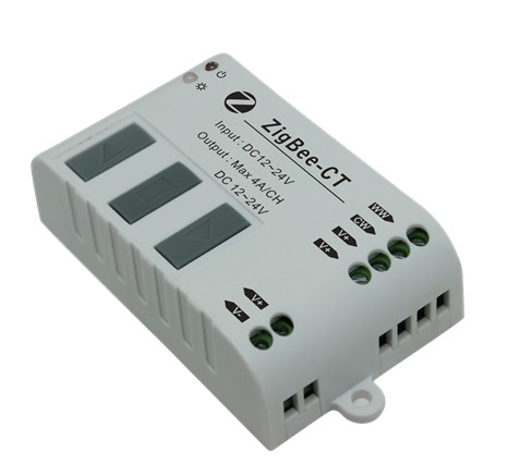
Short press can change built-in mode, long press over 3 seconds can open or close output |
|
3 |
Parameter decreasing set key |
Decrease the brightness of light
|
|
4 |
Power input negative pole |
Provide the power to control circuit and load output |
|
5 |
Power input positive pole |
|
|
6 |
Anode output |
Connected to anode common port of color temperature led strips |
|
7 |
||
|
8 |
output channel 1 |
Connected to the cold control port of color temperature led strips |
|
9 |
output channel 2 |
Connected to the warm control port of color temperature led strips |
Working State Directions
|
Number |
Indicator light |
Explanation |
|
10 |
Power indicator light |
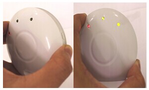
Power indicator light keeps on, showing normal power supply |
|
11 |
Status indicator light |
Green flash once, showing receiving host data |
|
Green light keeps on, showing long press the key |
||
|
Yellow light keeps on, showing being access network |
||
|
Red light keeps on, showing failure to access network |
Operation procedure
1. Plug in power supply(number 4,5) and led strips(number 6,7,8,9) on the basis of interface specification diagram.
2. Connect power supply to the master and slave, make sure the voltage is correct. At this moment, power indicator light (number 10) become red.
3. Operation of the slave joining host network
(1)Press MATCH of the master until signal light of the master is on, then let go of your hands.

(2)Then press together the slave parameter increasing set key(number 1) with parameter decreasing set key (number 3)for 3 seconds until signal light(number 11) become yellow.

4. After the slave successfully join host network, signal light(number 11) will go out. On the master, only power light is on, otherwise it shows failure to access network, if so, please repeat the step 3.
( Please refer to Illustration of working condition for signal light information when normal working, interface specification for key operation when invocating built-in mode)
Built-in mode table
User can use two-channel color temperature led strips to match up with phone control software, which can make user defined color temperature brightness change come true. Built-in mode table as below:
|
Number |
Brightness proportion |
Remark |
Number |
Brightness proportion |
Remark |
|
1 |
C:0% W:100% |
Adjustable brightness |
12 |
C:55%W:45% |
Adjustable brightness |
|
2 |
C:5% W:95% |
13 |
C:60% W:40% |
||
|
3 |
C:10% W:90% |
14 |
C:65% W:35% |
||
|
4 |
C:15% W:85% |
15 |
C:70% W:30% |
||
|
5 |
C:20% W:80% |
16 |
C:75% W:25% |
||
|
6 |
C:25% W:75% |
17 |
C:80% W:20% |
||
|
7 |
C:30% W:70% |
18 |
C:85% W:15% |
||
|
8 |
C:35% W:65% |
19 |
C:90% W:10% |
||
|
9 |
C:40% W:60% |
20 |
C:95% W:5% |
||
|
10 |
C:45% W:55% |
21 |
C:100% W:0% |
||
|
11 |
C:50% W:50% |
|
|
System Application Diagram

System Application Diagram
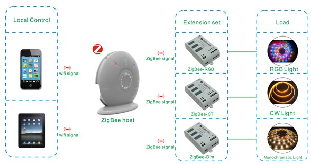
Notice: when the controller is being installed, in order to achieve the best controlling effect, the master should be placed in central position of each slave.
Notice
1. Please don't install controller in a seal off , high magnetic field and high-voltage area.
2. In order to reduce the risk of fire disaster and device damage caused by short circuit , please make sure correct connection.
3. Make sure that the controller is installed in ventilation to guarantee appropriate temperature.
4. Installation position of controller should be as near as possible to the router so as to ensure normal controlling;
5. Check if the voltage and power supply match with the controller.
6. Before switching on the power, please check if connection is correct, and use instrument to test if there is a short circuit.
7. Any problem , please do not open the shell of controller at will.
8. This manual is only applicable to this controller, if there is an update without prior notice.
|
No. |
Phenomenon |
Reason |
Solutions |
|
1 |
Load has no output |
1. out of power 2. output is overload 3. mistaken connection |
1. check the power 2. increase power amplifier 3. check the connection |
|
2 |
Wrong color |
Incorrect connection |
If the connection of led strips is corresponding to each other |
|
3 |
Failure to connect network |
Zigbee wireless network signal is poor |
Adjust installation site and rejoin network |
|
4 |
The end of led strips is dark when the length of it is too long |
1. output cable is too long 2. output cable diameter is too small 3. controller or power supply is overload |
1. shorten the length of cable 2. use cable with large diameter 3. increase power amplifier |
